Editing object points
For polygons and Bézier curves, Draw offers a complete set of tools that let you accurately edit the contour of an object. To edit other objects in the same way you must first convert them into curves. To do this, select the object, then right-click and choose Convert > To Curve or choose Modify > Convert > To Curve from the menu bar.
You can also convert the shapes to a polygon (Convert > To Polygon). With polygons the edge points are always connected with straight lines and not with curves. Some of the techniques described work equally with polygons as with curves.
Contents
An alternative way to change the form of basic shapes
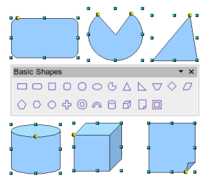
In current versions of OpenOffice.org many of the new shapes can be directly edited without having to first convert them to curves. You can recognize these objects by the presence of one (or more) yellow handles. Figure 12 shows a selection of shapes with such handles.
If you hover the mouse pointer over one of these handles and then drag it, you will be able to change the form of the shape; the exact type of change is dependent on the shape itself. The mouse pointer changes, as in the cylinder at the lower left of Figure 12, to a hand with index finger outstretched when hovered over one of these handles.
Examples of what you can do with this tool are rounding the corners of a rectangle or square, changing the angles of an arc or ellipse, or altering the control points of a circular or elliptical segment.
How curves work
Editing curves works on the basis of a method called Bézier curves*. The complete study of such curves goes beyond this scope of this Guide and only the basics of this powerful method of editing the contour of an object are covered here. Chapter 10 (Advanced Draw Techniques) provides more information on drawing and manipulating Bézier curves.
- Bézier curves were invented by Pierre Bézier, an engineer working with the Renault car manufacturer, who developed the technique in the 1960s. The technology was intended to make modeling the surface of vehicles easier.
The editing of a Bézier curve consists in principle of moving points and/or tangents passing through these points. Each tangent has two control points, one at each end, and a junction point where it meets the curve. The relative angle and distance between the control points determine the shape of the curve. Figure 13 shows several variations starting from a basic circle and changing only one point on the circle.
You can create many different shapes by moving either the junction point itself, or one or both of the round handle points at either end of the tangent.
Experimenting with moving the control point(s) of a tangent will yield countless variations of the basic starting shape. Draw offers even more possibilities when you use the functions on the Bézier curve toolbar.
The Edit Points toolbar
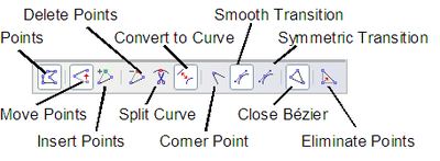
When you work in Edit Points mode, use the Edit Points toolbar, shown in Figure 14. This toolbar can be activated by View > Toolbars > Edit points. Once activated, it will appear whenever you select a curve and the Edit Points icon on the Drawing toolbar is active.
On this toolbar, some buttons will be active or inactive depending on the selected object and object point. With the Convert to Curve icon, you can determine for individual points whether their connection will be made with straight lines or with curves.
Only with curves are the icons for tangents activated. An object which contains no curves is treated as a polygon.
The role of the three buttons enabling you to choose the type of tangent is described in the following chapter. The other buttons are described here in relation to working examples.
The three kinds of tangent
Three buttons in the Edit Points Toolbar let you select the type of tangent and convert from one type to another. Only one of these buttons can be active at any given time.
| Content on this page is licensed under the Creative Common Attribution 3.0 license (CC-BY). |


