Dialog page - Shading
- Creating 3D objects
- Creating 3D bodies
- Producing 3D shapes
- Editing 3D objects
- 3D settings for 3D bodies
- Dialog page - Geometry
- Dialog page - Shading
- Dialog page - Illumination
- Dialog page - Textures
- Dialog page - Material
- 3D settings for 3D shapes
- Combining objects in 3D scenes
- Examples for your own experiments
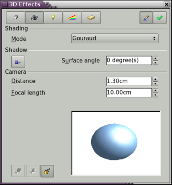
This dialog page (see Figure 24) offers functions for shading of the object surface, addition of shadows and “camera settings”.

Figure 24: The Shading dialog page
Shading is the rendering method, involving a consideration of the lighting ratios, which is used to produce curved 3D surfaces. The surfaces are broken down into small triangular segments. Draw offers three methods to produce this effect: Flat, Phong and Gouraud. The setting selected will apply to all objects in the 3D scene.
- Flat is the fastest and simplest method. For every individual segment a special color tone will be determined, based on the lighting ratio and the direction of the segment area. This tone is used for the whole area of the segment. The segmentation is clearly visible.
- Phong is the most time-consuming method. With this method, for each pixel the associated normal is determined by interpolation, based on the normals of the segment edges. This causes the segment area to appear curved and the segment intersections are no longer visible.
- Gouraud is a relatively quick method. It determines the color value for the segment corners and calculates the color value for every pixel through linear interpolation. The segment edges are still recognizable, but importantly are less so than with the flat method. The Gouraud method considers only light reflection on diffuse, reflecting surfaces (dispersal).

Figure 25: Flat, Phong and Gouraud shading
In Figure 25 the left sphere was rendered with flat shading, the middle with Phong and the right with Gouraud. The quality of the flat method is clearly different to the other two. The difference between Phong and Gouraud is small. With the Gouraud method the segments can be very faintly seen and rendered objects have a slightly less “shine” than with the Phong method.
All three methods function at the pixel level and as such, shadowing and mirroring inside the 3D scene is not possible in the way that ray tracing methods permit.
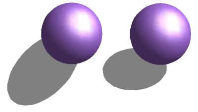
With the the button Shadow [[Image:]] you can provide a 3D object with a shadow. By changing the Surface angle you can influence the form of the shadow (see Figure 26). The left sphere has a surface angle of 0° - the paper lies at right angles behind the object – while the right sphere has a surface angle of 45°. With 90° the paper would be directly under the object.

Figure 26: Shadows using different surface angles
The shape and size of the the shadow are influenced also by the lighting properties. These can be adjusted on the dialog page Illumination. Multiple light sources are at this time not supported. The shadow properties can be set for individual objects in a drawing but the shadow produced will be that of the entire scene where objects form part of a 3D scene.
It is possible to set the shadow property for single objects using the property “Area”. The shadow will then be shown with the color selected in the shadow dialog, however again the representation of the lighting of the scene will determine the end result of the entire scene. In this way, colored shadows, with different distance to the object, color and transparency effects are possible.
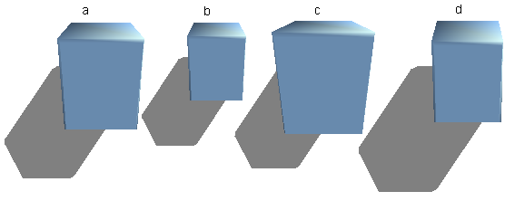
In the field Camera of the shading dialog the settings of the virtual camera can be changed. These settings relate only to the view in central projection and apply to the entire 3D scene. With the Distance parameter the spacing between the camera and scene is adjusted. The default value for an extruded body is equal to the predetermined depth. With equal length edges front and rear the effect at large distances is quite small. The standard value of Focal length is 10cm. It has the same significance as with an ordinary camera. Larger focal lengths work like a telephoto lens, smaller like a wide angle lens. The effect that changes in the camera settings have on an object are shown in Figure 27.

Figure 27: Effect of camera settings
Picture a shows the 3D object with the standard settings. The individual changes are listed in the following table.
| a | b | c | d | |
| Distance: | 0.81 cm | 3.81 cm | 0.81 cm | 0.81 cm |
| Focal length: | 10 cm | 10 cm | 5 cm | 15 cm |
| Content on this page is licensed under the Creative Common Attribution 3.0 license (CC-BY). |