User:Regina/MYDrafts4
Problems With Angle and Gradient Definitions in ODF1.2
Contents
Missing Definition of Orientation
ODF1.2 specification does not proper define orientation for drawings. Here are two suggestions.
Coordinate System
There are two common ways to orientate a Cartesian coordinate system.
 |
 |
Only when the orientation is determined, terms like "clockwise" are unambigious. Such orientation rule is missing in ODF 1.2.
Suggestion:
If a rule refers to a two-dimensional coordinate system, a Cartesian coordinate system in screen orientation (see figure ##) is used. The directions "clockwise", "counter clockwise", and the edge descriptions "left", "top", "right" and "button" are accordingly defined as shown in figures [##] to [##].
 |
 |
Positive Orientation
This proposals is based on comments by Armin Le Grand on the mailing list ooo-dev@incubator.apache.org.
A rotation around the origin has a positive orientation, if it moves the point (1|0) from the positive part of the X-axis over the first quadrant of the coordinate system towards the point (0|1) on the positive part of the Y-axis. A rotation with positive orientation is described by a positive angle.
Advantage: This definition is independent of the orientation of the coordinate system. It leads on a coordinate system with “screen orientation” also to a clockwise rotation for a positive rotation angle.
 |
 |
| Same definition by "moving from point (1|0) over first quadrant" | |
Errors in Attribute draw:transform
These suggestions are all about section 19.228. (Because of the Wiki markup I skipped the characters < and >).
I suggest to give an example for each single transformation value, with reference to the corresponding transformation matrix and illustrate that example .
| Original | Problems and Suggestions |
|---|---|
| rotation by rotate-angle degrees | AOO, LO and Microsoft Office use the angle in rad not in deg.
Suggestion: Adapt ODF1.2 to the practice. Specify unit rad for values rotate, skewX and skewY in attribute draw:transform. Deprecate the attribute draw:transform and use attribute svg:transform instead in ODF1.3. If you follow this suggestion the following examples need to be adapted. |
| The whole original text is very near to SVG section 7, but a reference is missing. | |
| matrix(a b c d e f), specifies a transformation in the form of a transformation matrix of six values. "The values describe a standard 3x2 homogeneous transformation matrix in column-major order, where the right column (e, f) describes the translation. | Typo: The quotation mark before 'The values' has to be removed.
Problem: A standalone translation needs parameter with units. Here this rule is missing. Suggestion: Add the sentence: The values e and f are lengths (18.3.18). |
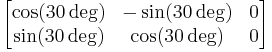
| rotate(rotate-angle), specifies a rotation by rotate-angle degrees about the origin of the shapes coordinate system. | The orientation of the rotation is missing. I suggest not to use "clockwise" but to define it by an equivalent matrix.
Suggestion: Example: The value rotate(30) corresponds to the transformation matrix  |
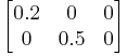
| scale( sx [ sy ]), specifies a scale operation by sx and sy. | It is not clear, that not only the object is scaled.
Suggestion: Example: The value scale(0.2 0.5) corresponds to the transformation matrix  |
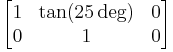
| skewX(skew-angle), specifies a skew transformation by rotate-angle degrees along the x-axis. | Typo: "rotate-angle" should be "skew-angle". (Already tracked in OFFICE-3755.)
Here is neither clear between which rays the angle is measured, nor what direction is used. Suggestion: Example: The value skewX(25) corresponds to the transformation matrix  |
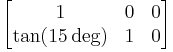
| skewY(skew-angle), specifies a skew transformation by rotate-angle degrees along the y-axis. | Same as skewX, typo "rotate-angle" and unclear angle.
Suggestion: Example: The value skewY(15) corresponds to the transformation matrix  |
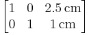
| translate( tx [ty]), specifies a translation by tx and ty, where tx and ty are lengths (18.3.18). | In contrast to the other transformations, the parameters need a unit here. Therefore an example is useful.
Suggestion: Example: The value translate(2.5cm 1cm) corresponds to the transformation matrix
|
Problems with draw:gradient
draw:angle
ODF 1.2 specifies in section 19.112 draw:angle
"The draw:angle attribute specifies an angle that rotates the axis at which the gradient values are interpolated. This attribute is ignored for radial style gradients."
and in section 18.3.1 for the data type angle
"An angle, as defined in §4.1 of [SVG]. An angle is a double value that may be followed immediately by one of the following angle unit identifiers: deg (degrees), grad (gradiants) or rad (radians). If no unit identifier is specified, the value is assumed to be in degrees."
Problem: Unit of the angle
Apache OpenOffice, LibreOffice and Microsoft Offic use the unit 0.1deg, Gnumeric uses the unit degree.
Solution: Remove the reference to data type angle from draw:angle and define directly, "The value of the attribute draw:angle has the data type integer and is interpreted as 0.1deg". Do this as errata to ODF 1.2.
Reasoning: In Gnumeric this is only used for filling rectangles in charts. If the gradient of older documents look different it has no big impact. But a lot of complex drawings and presentations has been produced by the other application and much more users would be impacted, if the gradient rotation changes in old documents.
Problem: Orientation of the gradient rotation
With a positive value for the angle, the rotation should be "positive" in the sense described above. That is, on a screen orientated coordinate system the rotation should be clockwise. But OpenOffice.org and related application rotate counter clockwise. That is not unusual, for example in Corel Draw 12, a positive rotation angle in the UI leads to a counter clockwise gradient rotation too.
Solution: Deprecate the attribute draw:angle. Use instead the attribute svg:gradientTransform as it is defined in SVG 13.2. That attribute can already be used in svg:linearGradient and svg:radialGradient. This should be done at latest from ODF1.3. But perhaps it is possible to deprecate the attribute draw:angle already in an errata and allow applications to use the attribute svg:gradientTransform already in the element draw:gradient in ODF1.2.
draw:style="radial"
ODF 1.2 specifies in section 19.218.2 <draw:gradient>
"radial: defines a gradient where the colors are blend along the radius from the center of a circle as defined with the draw:cx and draw:cy attributes. The outside of the circle is filled with the end color."
Problem: Size of the circle
It is not clear, how large the circle is. Variants:
(1) The length of the diameter of the circle equals the length of the diameter of the bounding box, independent of the position of the center of the circle
(2) The length of the diameter of the circle equals the length of the shorter edge of the bounding box, independent of the position of the center of the circle
(3) The length of the diameter of the circle equals the length of the larger edge of the bounding box, independent of the position of the center of the circle
(4) The length of the radius of the circle equals the largest distance from the center of the circle to a corner of the bounding box.
(5) The length of the radius of the circle equals the smallest distance from the center of the circle to a corner of the bounding box.
All variants refer to the bounding box. Therefor that has to be defined too. Because the term "bounding box" is used in other places too, a common definition is needed.
| Apache OpenOffice uses method (1).
Microsoft PowerPoint 2010 seems to use method (4) for the ppt file format. |
 |
Solution
Add sentence (1)
Problem: Direction of blending
| Original | Problems and Solutions |
|---|---|
| radial: defines a gradient where the colors are blend along the radius from the center of a circle as defined with the draw:cx and draw:cy attributes. The outside of the circle is filled with the end color. | The implementations Apache OpenOffice and LibreOffice blend from start color outside the circle to the end color in the center of the circle.
There are a lot of documents out, that use the blending direction from out to inside, so changing the standard to the reality would be reasonable. On the other hand defining blending from center to outside corresponds to the definition in SVG and CSS3, which makes the current rule in ODF1.2 reasonable too. ODF1.1 has no setting for the direction. End color and start color are not simply exchangeable, because the attribute draw:border depends on the setting of the start color. No solution yet. Ideas: (1) Let the current attribute values as vague as in ODF1.1 and let application handle them as they want. Add additional values in ODF1.3 with exact description of the directions in a way that it corresponds to the SVG standard. The old values can be marked 'deprecated'. (2) Add a parameter for ODF1.3 (as it is possible in CSS3), which determines the direction, so that it is unambiguous for new documents. And say, that the direction depends on the application and its drawing engine, if the parameter is missing, so that older documents can be used as now. (3) Change the ODF1.2 standard to the actual existing implementations.
|
draw:style="square"
ODF 1.2 specifies in section 19.218.2 <draw:gradient>
"square: defines a gradient that produces a square blend, imitating the visual perspective in a corridor or the aerial view of a pyramid. Also known as "box gradient" and "pyramidal gradient". The center of the square is defined with the draw:cx and draw:cy attributes. The width and height of the square is the minimum value of either the width or the height of the filled area. The outside of the square is filled with the end color. "
Problem: Reference "filled area"
| Original | Problems and Solutions |
|---|---|
| The width and height of the square is the minimum value of either the width or the height of the filled area. | Problem: The "width or the height of the filled area" is undefined for an object with combined subpathes.
Solution: Do not use "filled area" as reference but "bounding box".  |
Problem: Size of the square
| Original | Problems and Solutions |
|---|---|
| The width and height of the square is the minimum value of either the width or the height of the filled area. | Problem: Apache OpenOffice and LibreOffice do not use the minimum but the maximum value.
Solution: Change "minimum" to "maximum" and use the bounding box as reference. File:SquareMultiObjectsBoundingBoxShot.png The longer edge of the bounding box equals the edge of the square, independent of the position of the center. |
Problem: Direction of blending
There are the same problems as for the value "radial".
draw style "linear"
Original in 19.218.2 draw:gradient
- Linear: defines a gradient where the colors blend along the linear axis of the gradient. The axis of the gradient is specified with the draw:angle attribute clockwise to the vertical axis.
Original in 19.122 draw:angle
- The draw:angle attribute specifies an angle that rotates the axis at which the gradient values are interpolated.
Problems
(1) Typo: The attribute value "linear" should be completely in lower case as the other values.
(2) It is unclear in which direction the colors blend, it could be "from top to bottom" in visual description or "in positive y-axis direction" in mathematical description. A description "from top to bottom" would need an additional rule about the y-axis orientation.
| File:LinearGradientWithUnclearDirection.png Missing rule for directions allows different interpretation of blending. |
(3) In addition to the problems with draw:angle, which are already described above, here the reference to the y-axis is incomplete. Without a rule about the y-axis orientation the mathematical operation “rotation” from 19.218.2 draw:angle might conflict with the visual description “clockwise” in 19.218.2 draw:gradient.
| File:PositiveGradientRotationMathematical.png Rotation by +30deg, if mathematical orientation is assumed |
File:PositiveGradientRotationVisualClockwise.png Rotation by +30deg, if screen orientation is assumed |